Télécharger la présentation
La présentation est en train de télécharger. S'il vous plaît, attendez

1
Les processus métiers : concepts, modèles et systèmes
Claude Godart Université de lorraine. Esstin

2
Organisation du cours Introduction Concepts et notations
Modélisation des processus Analyse qualitative des processus Analyse quantitative des processus Systèmes de gestion de processus Processus transactionnels Découverte de processus Conclusion

3
Chapitre 4 : Systèmes de gestion de processus
Claude Godart Université de lorraine. Esstin

4
Contenu Concepts généraux Systèmes de gestion de processus
Modèle de référence de la WfMC Systèmes de gestion de processus Systèmes intégrés (Bonita, IBM MQ Workflow) Bibliothèques de processus PVM, WWF Les services Web BPMN vers BPEL4WS
 Bibliothèques de processus. PVM, WWF. Les services Web. BPMN vers BPEL4WS.")
5
Introduction (1) Objectif d’un système de gestion de processus (SGP) :
Décrire la logique d’un processus et en contrôler le respect à l’exécution Assurer l’interface entre ces fonctionnalités, les utilisateurs et les programmes d’application Concrètement Des outils variés avec des architectures variées Mais un ensemble standardisé de composants fonctionnels (modèle de la WfMC) Si on retrouve ces fonctionnalités totalement ou en partie dans les outils, leurs mises en œuvre sont assez diverses
 Si on retrouve ces fonctionnalités totalement ou en partie dans les outils, leurs mises en œuvre sont assez diverses.")
6
Introduction (2) Deux grandes approches :
Les suites intégrées de gestion de processus Solution complète et générale pour une large gamme d’applications distribuées Bonita, IBM MQ Workflow, W4 … Les bibliothèques de processus Un ensemble de composants basiques pour une définition à la carte de SGP légers souvent embarqués dans des applications plus larges Process Virtual Machine, Window Workflow Foundation

7
Les composants d’un SGWf (WfMC)
")
8
Le modèle de référence de la WfMC

9
Le service d’exécution des processus
Création et terminaison des cas Navigation au sein d’un cas en interprétant le modèle de processus en fonction du contexte d’exécution Transfert des données entre les conteneurs d’entrée et de sortie des activités Affectation des bons de travail dans les corbeilles des ressources (en fonction des rôles, …) Liaison des activité aux applications externes comme défini dans le modèle informationnel Capture des données historiques nécessaires à la supervision et à l’audit des processus
 Liaison des activité aux applications externes comme défini dans le modèle informationnel. Capture des données historiques nécessaires à la supervision et à l’audit des processus.")
10
Le service de définition des processus
La modélisation des processus en utilisant des notations (chapitres 2 et 3) La modélisation des rôles, des ressources et les liaisons statiques entre les activités et les rôles, les activités et les applications externes L’analyse et la simulation des processus (structuration, vivacité, blocage …)
 La modélisation des rôles, des ressources et les liaisons statiques entre les activités et les rôles, les activités et les applications externes. L’analyse et la simulation des processus (structuration, vivacité, blocage …)")
11
La gestion des applications clientes
La gestion des sessions la gestion des corbeilles de bons de travail des participants en fonction des rôles La possibilité de trier et d’organiser les bons de travail L’instanciation, le démarrage, la suspension d’un processus, d’une activité L’information sur l’état du processus et des activités

12
La gestion des applications invoquées
La gestion des connexions, déconnexions aux applications La gestion des activités invoquant une application Démarrage/suspension/redémarrage/abandon d’une activité, gestion des signaux, notification de terminaison La gestion des données en entrée et en sortie des applications

13
L’interopérabilité des processus (1)
Mode d’interopérabilité (a) mode chaîné (b) mode hiérarchique (c) mode synchronisation parallèle (d) mode pair-à-pair Des notations pour l’interopérabilité (WfXML, XPDL) Supporte les processus inter-organisationnels (chapitre 8)
 mode chaîné. (b) mode hiérarchique. (c) mode synchronisation parallèle. (d) mode pair-à-pair. Des notations pour l’interopérabilité (WfXML, XPDL) Supporte les processus inter-organisationnels (chapitre 8)")
14
L’interopérabilité des processus (2)
")
15
La supervision des processus
La gestion (évaluation, ajustement) des rôles, des utilisateurs La reconfiguration pour améliorer des paramètres (performance …) L’inspection d’un processus en cours d’exécution La modification « à la main » d’une instance de processus La journalisation des information d’audit Des heuristiques d’audit (taux moyen d’attente, d’exécution, taux d’utilisation des ressources …)
 des rôles, des utilisateurs. La reconfiguration pour améliorer des paramètres (performance …) L’inspection d’un processus en cours d’exécution. La modification « à la main » d’une instance de processus. La journalisation des information d’audit. Des heuristiques d’audit (taux moyen d’attente, d’exécution, taux d’utilisation des ressources …)")
16
Les utilisateurs d’un SGP
Les concepteurs et analystes de processus Modélisation a priori et re-ingénierie du modèle de processus, surveillance de l’exécution, analyse des traces d’exécution L’administrateur de processus Responsable du fonctionnement d’un processus à l’exécution; est informé de tout dysfonctionnement et réagit en fonction L’administrateur opérationnel Responsable du bon fonctionnement du matériel et du logiciel Les utilisateurs finaux On peut distinguer : les clients (simple utilisateurs, par exemple Web) , les techniciens métiers qui peuvent gérer des activités complexes, le service support qui fait le lien entre les deux.
 , les techniciens métiers qui peuvent gérer des activités complexes, le service support qui fait le lien entre les deux.")
17
Les systèmes intégrés de gestion de processus

18
Objectifs Proposer l’ensemble des fonctionnalités
Proposer une large gamme d’outils pour l’intégration au système d’information de l’organisation hôte (interface BD …) Assurer un haut niveau de sûreté et de fiabilité pour garantir la continuité de l’exploitation Exemples : Bonita, IBM MQ Workflow
 Assurer un haut niveau de sûreté et de fiabilité pour garantir la continuité de l’exploitation. Exemples : Bonita, IBM MQ Workflow.")
19
Bonita Première version LGPL en 2004 Nova Bonita depuis 2008
Contributeur à, et utilisateur de la PVM (Process Vitual Machine) Aujourd’hui Bonita, un des leaders du BPM en France :
 Aujourd’hui Bonita, un des leaders du BPM en France :")
20
Bonita Les transparents qui suivent ont été réalisés avec la version de Bonita disponible en 2009 Depuis, le système a évolué mais l’architecture présentée est encore représentative

21
Architecture

22
Architecture Architecture multitiers Java Enterprise Edition
Toutes les interactions avec les utilisateurs se font à travers la « console workflow » Le moteur de processus gère la description et l’exécution des processus, ainsi que l’interface avec les programmes d’exécution

23
Implantation Développement Java Enterprise Edition (J2EE) :
Entity beans pour la sauvegarde des informations Java Authentification and Authorization services pour la gestion des droits d’accès Java Transaction Service pour la gestion des transactions (longues) Java Messaging pour la gestion des alertes Java Mail pour l’envoi des s
 Java Messaging pour la gestion des alertes. Java Mail pour l’envoi des s.")
24
Gestion des utilisateurs 4 profils principaux

25
Profil utilisateur Démarrage d’un processus Traitement des activités
Visualisation des processus et des activités dans lesquels il est impliqué Lister les informations sur les activités terminées

26
Edition d’une condition

27
Etat d’une instance de processus

28
Profil administrateur
Orienté système Gère la base de données des utilisateurs Définit le profil des utilisateurs

29
Gestion des rôles et des utilisateurs
Par défaut, Bonita fournit un référentiel de gestion des utilisateurs s’appuyant sur une base de données …

30
Gestion des rôles et des utilisateurs
… mais ce référentiel peut être remplacé ou interconnecté à un référentiel d’entreprise existant, typiquement LDAP

31
Profil opérateur Peut intervenir sur le déroulement des instances de processus Gestion des erreurs en utilisant les traces et les historiques

32
Historique d’un processus

33
Le moteur d’exécution Environnement Java EE
Données des processus gérées par le container EJB du serveur d’applications Stockage des données par le moteur de transformation Objet/Relationnel Notification des clients, des outils … avec JMS Interprète des descriptions de processus en XPDL Les activités, les transitions s’exécutent comme des transactions JTS Connectivité vers des systèmes d’information par Web services ou connecteurs Java Connector Architecture Possibilité d’associer des actions aux événements du cycle de vie des activités (Hooks)
")
34
L’outil de définition de processus
Outil graphique ProEd qui génère en sortie des description XPDL Définition des activités, des transitions, des participants, des hooks, des sous-processus, des blocs d’activités Plugin Eclipse Formulaires de définition des activités

35
Editeur ProEd

36
Formulaire de définition d’activité

37
Formulaire d’une activité

38
Le processus de gestion de voyage avec ProEd

39
Introduction de Swimlanes

40
Exemple de Hook dans un processus XPDL

41
Exécution d’un Hook

42
Administration de Bonita

43
Gestion des transactions
Gestion de processus de longue durée Chaque opération système d’écriture et de mise à jour de l’état du processus lance une transaction Java EE La gestion des opérations Commit et Rollback est déléguée au container EJB Il est possible de choisir la politique de gestion transactionnelle des hooks Néanmoins, il s’agit de transactions « classiques », pas de transactions avancées comme proposées WS-Coordination/Transaction (Chapitre 5)
")
44
IBM MQ Workflow Système intégré complet Architecture à 3 niveaux
Le workflow comme un intergiciel entre le serveur de base de données et les applications clients Intégration par échange de message, Plus grande fiabilité, passage à l’échelle Bénéficie du contexte IBM

45
Architecture

46
Intégration par queues de messages

47
API IBM MQ Workflow

48
Conclusion sur les systèmes intégrés
Des fonctionnalités de plus en plus standardisées mais avec des mises en œuvre différentes Bonita Une belle réussite du monde du logiciel libre Une contribution à la PVM Création en 2009 de la société BonitaSoft IBM MQ Workflow Le standard du monde IBM Bénéficie du contexte IBM (intégration fiable par queues de messages)
")
49
Les bibliothèques de processus

50
Objectifs Un ensemble de composants basiques Deux approches :
pour une définition à la carte de processus légers généralement à embarquer dans des applications plus larges Deux approches : La PVM du monde Java La WWF du monde Microsoft

51
La Process Virtual Machine
Noyau de SGP du monde Java Fondé sur JBPM (Java Business Process Management, et Bonita ( La PVM propose un noyau de modèle de processus basique mais extensible

52
Principes Tous les modèles ont en commun Mais varient en fonction de :
D’être représentés comme un graphe pour faciliter la communication D’exprimer d’une façon ou d’une autre des flots d’exécution D’être potentiellement de longue durée et d’inclure des états d’attente d’événements Mais varient en fonction de : Du modèle de persistance choisi Des types de transactions qui encapsulent les activités Des services annexes utilisés Des liaisons avec les applications de l’entreprise

53
Noyau de base Modèle de graphes de processus, définition du comportement d’un nœud
public interface Executable { void execute (Execution execution) throws Exception; }
 throws Exception; }")
54
Modèle d’exécution de PVM
A une exécution est associée un pointeur qui pointe sur le noeud courant L’exécution attend un événement externe qui déclenche la méthode proceed du nœud courant qui permet de décider quelle transition franchir

55
Définition d’un nœud de type Tâche humaine
public class TaskNode implements Executable { String taskName; public void execute (Execution execution) { //affecter une personne responsable de cette tâche User assignedUser = calculateUser(taskName, execution); //créer la tâche Task task = new Task(taskName, assignedUsr, execution); //ajouter la tâche au répertoire de tâche TaskRepository taskRepository = execution.getContext().getTaskRepository(); taskRepository.addTask(task); }
 { //affecter une personne responsable de cette tâche. User assignedUser = calculateUser(taskName, execution); //créer la tâche. Task task = new Task(taskName, assignedUsr, execution); //ajouter la tâche au répertoire de tâche. TaskRepository taskRepository = execution.getContext().getTaskRepository(); taskRepository.addTask(task); }")
56
Définition d’un nœud de type Courrier
public class Node implements Executable { String recipient; String subject; String text; public void execute (Execution execution) { // envoyer le mail send (recipient,subject,text,execution); // propager l’exécution execution.proceed(); }
 { // envoyer le mail. send (recipient,subject,text,execution); // propager l’exécution. execution.proceed(); }")
57
Extensions (1)
")
58
Extensions (2)
")
59
Window Workflow Foundation
Objectif semblable à PVM Mais conçu pour le monde .NET Bénéficie du contexte et permet de générer aussi bien : Des processus classiques Des flots de page d’un site Web Des processus de circulation de documents

60
Architecture : 3 couches principales

61
Définition d’une activité en étendant une activité existante
public class CreateActivity : Activity { public string Assignee { ... } public DateTime DueDate { ... } protected override ActivityExecutionStatus Execute( ActivityExecutionContext context) { // assign task to assignee... return ActivityExecutionStatus.Closed; }
 { // assign task to assignee... return ActivityExecutionStatus.Closed; }")
62
Outil de modélisation de processus (intégré à Visual Studio)
")
63
Hébergement d’un processus
Chaque application de la famille .NET 2007 intégre WWF en son coeur

64
Hébergement du moteur d’exécution
WorkflowRuntime runtime = new WorkflowRuntime(); runtime.AddService(...) WorkflowInstance instance = runtime.CreateWorkflow(...); instance.Start(); Guid id = instance.InstanceId; Instanciation du moteur de processus, ajout de services, création d’une instance de processus, démarrage de l’instance ….
; runtime.AddService(...) WorkflowInstance instance = runtime.CreateWorkflow(...); instance.Start(); Guid id = instance.InstanceId; Instanciation du moteur de processus, ajout de services, création d’une instance de processus, démarrage de l’instance ….")
65
Les bibliothèques de processus Conclusion
Permettent de répondre à des demandes plutôt simples sans gros investissement ni gros déploiement Un effort de programmation est néanmoins encore nécessaire, mais beaucoup moins important qu’en partant de rien Et apporte la garantie d’une forme d’interopérabilité

66
Les services Web Les activités comme des services Web La logique en
BPEL (Business Process Execution Language) Syntaxiquement un milieu entre BPMN et XPDL REST
 Syntaxiquement un milieu entre BPMN et XPDL. REST.")
67
Les activités comme des services Web
… Service 1 Service 2 Service 3 Service 4 … Service n Bus ( … BPEL … ) Appli 1 Appli 2 Appli 3 Appli n Appli n+1
 Appli 1. Appli 2. Appli 3. Appli n. Appli n+1.")
68
Service Web

69
Appel de service

70
Composition de service

71
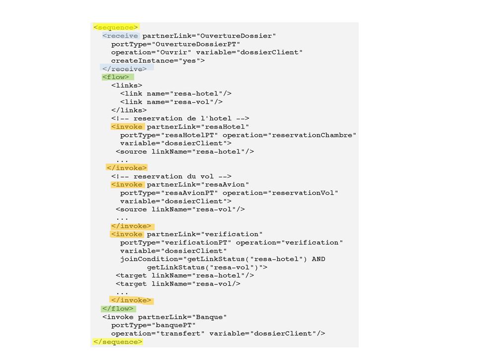
Business Process Execution Language 4 Web Services (BPEL4WS en court, BPEL en encore plus court)
Constructeurs Activités de base : <assign> : gestion des variables <invoke> : appeler un service <receive> : recevoir une réponse Flot de contrôle : <sequence> : exécution en séquence <while> : boucle tant-que <switch> : conditionnelle <flow> : exécution parallèle …

72
Exemple <sequence> <switch> <flow>
Partie décrite en BPEL

74
Un exemple plus complet
Les transparents 76 à 100 viennent de cette présentation accessible sur leWeb : 3146 Modeling BPEL4WS Richard C. Gronback Sr. Product Manager, Together Products Borland Software Corporation Conference Borland 2014

75
BPMNBPEL4WS Example

76
BPMNBPEL4WS Loop

77
BPMNBPEL4WS Loop

78
Mapping Example Let’s explore the diagram elements and mappings of BPMN to BPEL4WS Domain is Voting Process From BPMN Specification Focus here is on Discussion Cycle sub-process for simplicity

79
Voting Process

80
Mapping Discussion Cycle
Discussion Cycle sub-process in BPD (of BPMN) maps to BPEL4WS process Invocation from higher-level process means it will start with receive and end with reply <process name="Discussion_Cycle"> <sequence> <receive partnerLink="Internal" portType="tns:processPort" operation="call_Discussion_Cycle" variable="processData" createInstance="Yes"/> . . . <reply partnerLink="Internal" portType="tns:processPort" operation="call_Discussion_Cycle" variable="processData"/> </sequence> </process>
 maps to BPEL4WS process. Invocation from higher-level process means it will start with receive and end with reply. <process name= Discussion_Cycle > <sequence> <receive partnerLink= Internal portType= tns:processPort operation= call_Discussion_Cycle variable= processData createInstance= Yes /> <reply partnerLink= Internal portType= tns:processPort operation= call_Discussion_Cycle variable= processData /> </sequence> </process>")
81
Discussion Cycle

82
Announce Issues The “Announce Issues for Discussion” task maps to a BPEL4WS invoke <invoke name="AnnounceIssuesforDiscussion" partnerLink="WGVoter" portType="tns: Port" operation="sendDiscussionAnnouncement" inputVariable="processData"/>

83
Discussion Cycle

84
Parallel Paths The output of the “Announce Issues for Discussion” task follows 3 paths that map to a BPEL4WS flow element <flow> <invoke name="Moderate Discussion" … … <invoke name=" DiscussionDeadlineWarning" … <invoke name="CheckCalendarforConferenceCall" … </flow>

85
Discussion Cycle

86
Upper Parallel Path The Moderate Discussion task maps to a synchronous BPEL4WS invoke element <invoke name="Moderate Discussion" partnerLink="internal" portType="tns:internalPort“ operation="sendDiscussion“ inputVariable="processData“ outputVariable="processData"/> The Upper Parallel Path In the upper parallel path of the fork, the Task, “Moderate Discussion,” has a Timer Intermediate Event attached to its boundary. Because of this, • the Task is placed in its own scope with a faultHandlers. • The Task itself is mapped to a BPEL4WS invoke (synchronous), and will be placed in a lower-level flow, for reasons described below. The Timer Intermediate Event must be set up to create a fault at the appropriate time. To do this, • An eventHandlers is added to the scope. • An onAlarm is included in the eventHandlers and the for attribute is set to the duration that is defined in the Timer Intermediate Event. • The onAlarm contains a throw with a fault name after the Intermediate Event with “_Exit” appended. The catch of a faultHandlers will be triggered by the fault generated by the above throw. Since the Timer Intermediate Event leads direction to the Exclusive Gateway, there is no specific activity that must be performed in response the to time-out. The main purpose is to exit the Task. Thus, • A faultHandlers is added to the scope. • The catch in the faultHandlers has a faultName set to Intermediate Event with “_Exit” appended. • the catch will contain an empty activity.
, and will be placed in a. lower-level flow, for reasons described below. The Timer Intermediate Event must be set up to create a fault at the appropriate time. To do. this, • An eventHandlers is added to the scope. • An onAlarm is included in the eventHandlers and the for attribute is set to the. duration that is defined in the Timer Intermediate Event. • The onAlarm contains a throw with a fault name after the Intermediate Event with. _Exit appended. The catch of a faultHandlers will be triggered by the fault generated by the above throw. Since. the Timer Intermediate Event leads direction to the Exclusive Gateway, there is no specific. activity that must be performed in response the to time-out. The main purpose is to exit the. Task. Thus, • A faultHandlers is added to the scope. • The catch in the faultHandlers has a faultName set to Intermediate Event with _Exit appended. • the catch will contain an empty activity.")
87
Upper Parallel Path The Timer Intermediate Event on task boundary maps to scope element wrapping the invoke element with faultHandlers <scope> <invoke name="Moderate Discussion" … <faultHandlers> <catch faultName="7Days_Exit"> <empty/> </catch> </faultHandlers> …

88
Upper Parallel Path To create event at proper time, BPEL4WS eventHandlers added to the scope Why the onAlarm to throw to empty catch? … <eventHandlers> <onAlarm for="tns:OneWeek"> <throw faultName="7Days_Exit"/> </onAlarm> </eventHandlers> </scope>

89
Discussion Cycle

90
Middle Parallel Path The delay and Discussion Deadline Warning task map to BPEL4WS wait and invoke elements within a sequence element. <sequence> <wait name="Delay6daysfromDiscussionAnnouncement" for="P6D"/> <invoke name=" DiscussionDeadlineWarning" partnerLink="WGVoter" portType="tns: Port" operation="sendDiscussionWarning" inputVariable="processData"> </invoke> </sequence> The Middle Parallel Path The middle parallel path of the fork has a string of two objects. • Even though this series of objects appears in the middle of a BPEL4WS flow, they will be place within a sequence element. In these situations, the sequence will continue until there is a location in the Diagram where there are multiple incoming Sequence Flow. When more than one Sequence Flow converge it marks the end of a BPEL4WS structure (as determined by structures that have been created by upstream objects). In this case, the Parallel Gateway also marks the end of the higher-level flow. The sequence will be listed in the higher-level flow without a source sub-element. This means that the sequence will be instantiated when the higher-level flow begins since it has no dependencies on any other activity. The sequence will have two activities: • First, the Timer Intermediate Event used in this situation will map to a BPEL4WS wait (set to 6 days). • Second, the “ Discussion Deadline Warning” Task will map to an invoke that follows the wait. In addition, this invoke can be asynchronous since a response is not required. This means that the outputVariable will not be included. This middle path of the fork could have been configured in BPEL4WS without a sequence and with links instead. This is an example of a situation where a BPMN configuration may derive two possible BPEL4WS configurations. Since both BPEL4WS configurations will handle the appropriate behavior, it is up to the implementation of the BPMN to BPEL4WS derivation to determine which configuration will be used. BPMN does not provide any specific recommendation in these situations. However, the lower parallel path of the Process can also be modeled with a sequence or with links, and, to show how links would be used, this section of the Process will be mapped to elements in a flow that have dependencies specified by links.
. In this case, the Parallel Gateway also marks the end of the higher-level. flow. The sequence will be listed in the higher-level flow without a source sub-element. This. means that the sequence will be instantiated when the higher-level flow begins since it has no. dependencies on any other activity. The sequence will have two activities: • First, the Timer Intermediate Event used in this situation will map to a BPEL4WS wait. (set to 6 days). • Second, the Discussion Deadline Warning Task will map to an invoke that. follows the wait. In addition, this invoke can be asynchronous since a response is not. required. This means that the outputVariable will not be included. This middle path of the fork could have been configured in BPEL4WS without a sequence and. with links instead. This is an example of a situation where a BPMN configuration may derive. two possible BPEL4WS configurations. Since both BPEL4WS configurations will handle the. appropriate behavior, it is up to the implementation of the BPMN to BPEL4WS derivation to. determine which configuration will be used. BPMN does not provide any specific. recommendation in these situations. However, the lower parallel path of the Process can also. be modeled with a sequence or with links, and, to show how links would be used, this section. of the Process will be mapped to elements in a flow that have dependencies specified by links.")
91
Discussion Cycle

92
Lower Parallel Path The Check Calendar for Conference Call task maps to BPEL4WS invoke element. A decision on output can be handled with a BPEL4WS switch or reference links elements <invoke name="CheckCalendarforConferenceCall" partnerLink="internal" portType="tns:internalPort" operation="receiveCallSchedule" inputVariable="processData" outputVariable="processData"> … </invoke> The Lower Parallel Path The lower parallel path of the fork has a number of objects and, as just described above, will be mapped to BPEL4WS elements connected with links. The path also contains a Decision, which can map to a switch, as will happen later in the process, but in this situation the Decision is mapped to links controlled by transitionConditions. • The first object is a Task, which will map to an invoke (synchronous) that has two source elements referring to two of the links. There are two Target links because the Task is followed by the Gateway with its two Gates. This is done instead of a switch with a case and an otherwise. • The ConditionExpression for the Gate labeled “Yes” will map to the source element’s transitionCondition. The expression checks the value of the “ConCall” property (set in the previous Task) to see if there will be a conference call during the coming week. • The Gate labeled “No” has a condition of default. For a switch, this would map to the otherwise element. However, since a switch is not being used, the source element’s transitionCondition must be the inverse of all the other transitionConditions for the activity. The expression of the other source will be placed inside a “not” function. The invoke will be listed in the higher-level flow without a source sub-element. This means that the invoke will be instantiated when the higher-level flow begins since it has no dependencies on any other activity. The remaining elements of the higher-level flow will have a source element. Thus, they will not be instantiated until the source of the link has completed. • The “Yes” Gate from the Gateway leads to a Timer Intermediate Event, which will map to a wait. • The for element of the wait will set to for 9am PDT on the next Thursday. • This wait will have a target element that corresponds to the target element from the previous invoke. • The wait will also have a target element to link to the following invoke. • The “No” Gate from the Gateway leads to a merging Exclusive Gateway, which means that nothing is expected to happen down this path. Thus, this will map to an empty. • This empty will have a target element that corresponds to the target element from the • The Task for moderating the conference call follows the wait, which will map to an invoke (synchronous). • This invoke will have a target element that corresponds to the target element from the previous wait. There are three link elements in the flow: • One link will have a source of the first invoke and a target of the wait. • One link will have a source of the first invoke and a target of the empty. • One link will have a source of the first wait and a target of the last invoke. As mentioned above, the Parallel Gateway marks the end of the flow. Finally, there will be a reply at the end of the sequence that corresponds to the initial receive and lets the parent process know that the (sub) process has been completed. After the Parallel Paths are Joined The Task “Evaluate Discussion Progress” is intended to occur only when all the parallel paths have completed, and thus, it will • Map to an invoke that follows the closing of the flow.
 that has two source. elements referring to two of the links. There are two Target links because the Task is. followed by the Gateway with its two Gates. This is done instead of a switch with a case. and an otherwise. • The ConditionExpression for the Gate labeled Yes will map to the source element’s. transitionCondition. The expression checks the value of the ConCall property (set in. the previous Task) to see if there will be a conference call during the coming week. • The Gate labeled No has a condition of default. For a switch, this would map to the. otherwise element. However, since a switch is not being used, the source element’s. transitionCondition must be the inverse of all the other transitionConditions for the. activity. The expression of the other source will be placed inside a not function. The invoke will be listed in the higher-level flow without a source sub-element. This means that. the invoke will be instantiated when the higher-level flow begins since it has no dependencies. on any other activity. The remaining elements of the higher-level flow will have a source. element. Thus, they will not be instantiated until the source of the link has completed. • The Yes Gate from the Gateway leads to a Timer Intermediate Event, which will map to. a wait. • The for element of the wait will set to for 9am PDT on the next Thursday. • This wait will have a target element that corresponds to the target element from the. previous invoke. • The wait will also have a target element to link to the following invoke. • The No Gate from the Gateway leads to a merging Exclusive Gateway, which means. that nothing is expected to happen down this path. Thus, this will map to an empty. • This empty will have a target element that corresponds to the target element from the. • The Task for moderating the conference call follows the wait, which will map to an invoke. (synchronous). • This invoke will have a target element that corresponds to the target element from. the previous wait. There are three link elements in the flow: • One link will have a source of the first invoke and a target of the wait. • One link will have a source of the first invoke and a target of the empty. • One link will have a source of the first wait and a target of the last invoke. As mentioned above, the Parallel Gateway marks the end of the flow. Finally, there will be a reply at the end of the sequence that corresponds to the initial receive. and lets the parent process know that the (sub) process has been completed. After the Parallel Paths are Joined. The Task Evaluate Discussion Progress is intended to occur only when all the parallel paths. have completed, and thus, it will. • Map to an invoke that follows the closing of the flow.")
93
Lower Parallel Path In this case, decision maps to BPEL4WS links in source elements with corresponding transitionCondition attribute. <flow> <links> <link name="CheckCalendarforConferenceCalltoWaituntilThursday,9am"/> <link name="CheckCalendarforConferenceCalltoEmpty"/> … <invoke name="CheckCalendarforConferenceCall" <source linkName="CheckCalendarforConferenceCalltoWaituntilThursday9am" transitionCondition="bpws:getVariableProperty(processData,conCall)=true"/> <source linkName="CheckCalendarforConferenceCalltoEmpty" transitionCondition="not(bpws:getVariableProperty(processData,conCall)=true)"/> </invoke> The Lower Parallel Path The lower parallel path of the fork has a number of objects and, as just described above, will be mapped to BPEL4WS elements connected with links. The path also contains a Decision, which can map to a switch, as will happen later in the process, but in this situation the Decision is mapped to links controlled by transitionConditions. • The first object is a Task, which will map to an invoke (synchronous) that has two source elements referring to two of the links. There are two Target links because the Task is followed by the Gateway with its two Gates. This is done instead of a switch with a case and an otherwise. • The ConditionExpression for the Gate labeled “Yes” will map to the source element’s transitionCondition. The expression checks the value of the “ConCall” property (set in the previous Task) to see if there will be a conference call during the coming week. • The Gate labeled “No” has a condition of default. For a switch, this would map to the otherwise element. However, since a switch is not being used, the source element’s transitionCondition must be the inverse of all the other transitionConditions for the activity. The expression of the other source will be placed inside a “not” function. The invoke will be listed in the higher-level flow without a source sub-element. This means that the invoke will be instantiated when the higher-level flow begins since it has no dependencies on any other activity. The remaining elements of the higher-level flow will have a source element. Thus, they will not be instantiated until the source of the link has completed. • The “Yes” Gate from the Gateway leads to a Timer Intermediate Event, which will map to a wait. • The for element of the wait will set to for 9am PDT on the next Thursday. • This wait will have a target element that corresponds to the target element from the previous invoke. • The wait will also have a target element to link to the following invoke. • The “No” Gate from the Gateway leads to a merging Exclusive Gateway, which means that nothing is expected to happen down this path. Thus, this will map to an empty. • This empty will have a target element that corresponds to the target element from the • The Task for moderating the conference call follows the wait, which will map to an invoke (synchronous). • This invoke will have a target element that corresponds to the target element from the previous wait. There are three link elements in the flow: • One link will have a source of the first invoke and a target of the wait. • One link will have a source of the first invoke and a target of the empty. • One link will have a source of the first wait and a target of the last invoke. As mentioned above, the Parallel Gateway marks the end of the flow. Finally, there will be a reply at the end of the sequence that corresponds to the initial receive and lets the parent process know that the (sub) process has been completed. After the Parallel Paths are Joined The Task “Evaluate Discussion Progress” is intended to occur only when all the parallel paths have completed, and thus, it will • Map to an invoke that follows the closing of the flow.
=true /> <source linkName= CheckCalendarforConferenceCalltoEmpty transitionCondition= not(bpws:getVariableProperty(processData,conCall)=true) /> </invoke> The Lower Parallel Path. The lower parallel path of the fork has a number of objects and, as just described above, will. be mapped to BPEL4WS elements connected with links. The path also contains a Decision, which can map to a switch, as will happen later in the process, but in this situation the Decision. is mapped to links controlled by transitionConditions. • The first object is a Task, which will map to an invoke (synchronous) that has two source. elements referring to two of the links. There are two Target links because the Task is. followed by the Gateway with its two Gates. This is done instead of a switch with a case. and an otherwise. • The ConditionExpression for the Gate labeled Yes will map to the source element’s. transitionCondition. The expression checks the value of the ConCall property (set in. the previous Task) to see if there will be a conference call during the coming week. • The Gate labeled No has a condition of default. For a switch, this would map to the. otherwise element. However, since a switch is not being used, the source element’s. transitionCondition must be the inverse of all the other transitionConditions for the. activity. The expression of the other source will be placed inside a not function. The invoke will be listed in the higher-level flow without a source sub-element. This means that. the invoke will be instantiated when the higher-level flow begins since it has no dependencies. on any other activity. The remaining elements of the higher-level flow will have a source. element. Thus, they will not be instantiated until the source of the link has completed. • The Yes Gate from the Gateway leads to a Timer Intermediate Event, which will map to. a wait. • The for element of the wait will set to for 9am PDT on the next Thursday. • This wait will have a target element that corresponds to the target element from the. previous invoke. • The wait will also have a target element to link to the following invoke. • The No Gate from the Gateway leads to a merging Exclusive Gateway, which means. that nothing is expected to happen down this path. Thus, this will map to an empty. • This empty will have a target element that corresponds to the target element from the. • The Task for moderating the conference call follows the wait, which will map to an invoke. (synchronous). • This invoke will have a target element that corresponds to the target element from. the previous wait. There are three link elements in the flow: • One link will have a source of the first invoke and a target of the wait. • One link will have a source of the first invoke and a target of the empty. • One link will have a source of the first wait and a target of the last invoke. As mentioned above, the Parallel Gateway marks the end of the flow. Finally, there will be a reply at the end of the sequence that corresponds to the initial receive. and lets the parent process know that the (sub) process has been completed. After the Parallel Paths are Joined. The Task Evaluate Discussion Progress is intended to occur only when all the parallel paths. have completed, and thus, it will. • Map to an invoke that follows the closing of the flow.")
94
Lower Parallel Path From the “Yes” output from the decision, a BPEL4WS wait element is mapped. The wait element contains nested target and source elements with linkName attributes <flow> <links> … <link name="WaituntilThursday9amtoModerateConferenceCallDiscussion"/> <link name="CheckCalendarforConferenceCalltoWaituntilThursday,9am"/> <wait name="WaituntilThursday9am" for="P6DT9H"> <target linkName="CheckCalendarforConferenceCalltoWaituntilThursday9am"> <source linkName="WaituntilThursday9amtoModerateConferenceCallDiscussion"/> </wait> The Lower Parallel Path The lower parallel path of the fork has a number of objects and, as just described above, will be mapped to BPEL4WS elements connected with links. The path also contains a Decision, which can map to a switch, as will happen later in the process, but in this situation the Decision is mapped to links controlled by transitionConditions. • The first object is a Task, which will map to an invoke (synchronous) that has two source elements referring to two of the links. There are two Target links because the Task is followed by the Gateway with its two Gates. This is done instead of a switch with a case and an otherwise. • The ConditionExpression for the Gate labeled “Yes” will map to the source element’s transitionCondition. The expression checks the value of the “ConCall” property (set in the previous Task) to see if there will be a conference call during the coming week. • The Gate labeled “No” has a condition of default. For a switch, this would map to the otherwise element. However, since a switch is not being used, the source element’s transitionCondition must be the inverse of all the other transitionConditions for the activity. The expression of the other source will be placed inside a “not” function. The invoke will be listed in the higher-level flow without a source sub-element. This means that the invoke will be instantiated when the higher-level flow begins since it has no dependencies on any other activity. The remaining elements of the higher-level flow will have a source element. Thus, they will not be instantiated until the source of the link has completed. • The “Yes” Gate from the Gateway leads to a Timer Intermediate Event, which will map to a wait. • The for element of the wait will set to for 9am PDT on the next Thursday. • This wait will have a target element that corresponds to the target element from the previous invoke. • The wait will also have a target element to link to the following invoke. • The “No” Gate from the Gateway leads to a merging Exclusive Gateway, which means that nothing is expected to happen down this path. Thus, this will map to an empty. • This empty will have a target element that corresponds to the target element from the • The Task for moderating the conference call follows the wait, which will map to an invoke (synchronous). • This invoke will have a target element that corresponds to the target element from the previous wait. There are three link elements in the flow: • One link will have a source of the first invoke and a target of the wait. • One link will have a source of the first invoke and a target of the empty. • One link will have a source of the first wait and a target of the last invoke. As mentioned above, the Parallel Gateway marks the end of the flow. Finally, there will be a reply at the end of the sequence that corresponds to the initial receive and lets the parent process know that the (sub) process has been completed. After the Parallel Paths are Joined The Task “Evaluate Discussion Progress” is intended to occur only when all the parallel paths have completed, and thus, it will • Map to an invoke that follows the closing of the flow.
 that has two source. elements referring to two of the links. There are two Target links because the Task is. followed by the Gateway with its two Gates. This is done instead of a switch with a case. and an otherwise. • The ConditionExpression for the Gate labeled Yes will map to the source element’s. transitionCondition. The expression checks the value of the ConCall property (set in. the previous Task) to see if there will be a conference call during the coming week. • The Gate labeled No has a condition of default. For a switch, this would map to the. otherwise element. However, since a switch is not being used, the source element’s. transitionCondition must be the inverse of all the other transitionConditions for the. activity. The expression of the other source will be placed inside a not function. The invoke will be listed in the higher-level flow without a source sub-element. This means that. the invoke will be instantiated when the higher-level flow begins since it has no dependencies. on any other activity. The remaining elements of the higher-level flow will have a source. element. Thus, they will not be instantiated until the source of the link has completed. • The Yes Gate from the Gateway leads to a Timer Intermediate Event, which will map to. a wait. • The for element of the wait will set to for 9am PDT on the next Thursday. • This wait will have a target element that corresponds to the target element from the. previous invoke. • The wait will also have a target element to link to the following invoke. • The No Gate from the Gateway leads to a merging Exclusive Gateway, which means. that nothing is expected to happen down this path. Thus, this will map to an empty. • This empty will have a target element that corresponds to the target element from the. • The Task for moderating the conference call follows the wait, which will map to an invoke. (synchronous). • This invoke will have a target element that corresponds to the target element from. the previous wait. There are three link elements in the flow: • One link will have a source of the first invoke and a target of the wait. • One link will have a source of the first invoke and a target of the empty. • One link will have a source of the first wait and a target of the last invoke. As mentioned above, the Parallel Gateway marks the end of the flow. Finally, there will be a reply at the end of the sequence that corresponds to the initial receive. and lets the parent process know that the (sub) process has been completed. After the Parallel Paths are Joined. The Task Evaluate Discussion Progress is intended to occur only when all the parallel paths. have completed, and thus, it will. • Map to an invoke that follows the closing of the flow.")
95
Lower Parallel Path Following the wait, the Moderate Conference Call Discussion task maps to a BPEL4WS invoke element. <invoke name="ModerateConferenceCallDiscussion" partnerLink="internal" portType="tns:internalPort" operation="sendConCall" inputVariable="processData" outputVariable="processData"> <target linkName="WaituntilThursday9amtoModerateConferenceCallDiscussion"/> </invoke> The Lower Parallel Path The lower parallel path of the fork has a number of objects and, as just described above, will be mapped to BPEL4WS elements connected with links. The path also contains a Decision, which can map to a switch, as will happen later in the process, but in this situation the Decision is mapped to links controlled by transitionConditions. • The first object is a Task, which will map to an invoke (synchronous) that has two source elements referring to two of the links. There are two Target links because the Task is followed by the Gateway with its two Gates. This is done instead of a switch with a case and an otherwise. • The ConditionExpression for the Gate labeled “Yes” will map to the source element’s transitionCondition. The expression checks the value of the “ConCall” property (set in the previous Task) to see if there will be a conference call during the coming week. • The Gate labeled “No” has a condition of default. For a switch, this would map to the otherwise element. However, since a switch is not being used, the source element’s transitionCondition must be the inverse of all the other transitionConditions for the activity. The expression of the other source will be placed inside a “not” function. The invoke will be listed in the higher-level flow without a source sub-element. This means that the invoke will be instantiated when the higher-level flow begins since it has no dependencies on any other activity. The remaining elements of the higher-level flow will have a source element. Thus, they will not be instantiated until the source of the link has completed. • The “Yes” Gate from the Gateway leads to a Timer Intermediate Event, which will map to a wait. • The for element of the wait will set to for 9am PDT on the next Thursday. • This wait will have a target element that corresponds to the target element from the previous invoke. • The wait will also have a target element to link to the following invoke. • The “No” Gate from the Gateway leads to a merging Exclusive Gateway, which means that nothing is expected to happen down this path. Thus, this will map to an empty. • This empty will have a target element that corresponds to the target element from the • The Task for moderating the conference call follows the wait, which will map to an invoke (synchronous). • This invoke will have a target element that corresponds to the target element from the previous wait. There are three link elements in the flow: • One link will have a source of the first invoke and a target of the wait. • One link will have a source of the first invoke and a target of the empty. • One link will have a source of the first wait and a target of the last invoke. As mentioned above, the Parallel Gateway marks the end of the flow. Finally, there will be a reply at the end of the sequence that corresponds to the initial receive and lets the parent process know that the (sub) process has been completed. After the Parallel Paths are Joined The Task “Evaluate Discussion Progress” is intended to occur only when all the parallel paths have completed, and thus, it will • Map to an invoke that follows the closing of the flow.
 that has two source. elements referring to two of the links. There are two Target links because the Task is. followed by the Gateway with its two Gates. This is done instead of a switch with a case. and an otherwise. • The ConditionExpression for the Gate labeled Yes will map to the source element’s. transitionCondition. The expression checks the value of the ConCall property (set in. the previous Task) to see if there will be a conference call during the coming week. • The Gate labeled No has a condition of default. For a switch, this would map to the. otherwise element. However, since a switch is not being used, the source element’s. transitionCondition must be the inverse of all the other transitionConditions for the. activity. The expression of the other source will be placed inside a not function. The invoke will be listed in the higher-level flow without a source sub-element. This means that. the invoke will be instantiated when the higher-level flow begins since it has no dependencies. on any other activity. The remaining elements of the higher-level flow will have a source. element. Thus, they will not be instantiated until the source of the link has completed. • The Yes Gate from the Gateway leads to a Timer Intermediate Event, which will map to. a wait. • The for element of the wait will set to for 9am PDT on the next Thursday. • This wait will have a target element that corresponds to the target element from the. previous invoke. • The wait will also have a target element to link to the following invoke. • The No Gate from the Gateway leads to a merging Exclusive Gateway, which means. that nothing is expected to happen down this path. Thus, this will map to an empty. • This empty will have a target element that corresponds to the target element from the. • The Task for moderating the conference call follows the wait, which will map to an invoke. (synchronous). • This invoke will have a target element that corresponds to the target element from. the previous wait. There are three link elements in the flow: • One link will have a source of the first invoke and a target of the wait. • One link will have a source of the first invoke and a target of the empty. • One link will have a source of the first wait and a target of the last invoke. As mentioned above, the Parallel Gateway marks the end of the flow. Finally, there will be a reply at the end of the sequence that corresponds to the initial receive. and lets the parent process know that the (sub) process has been completed. After the Parallel Paths are Joined. The Task Evaluate Discussion Progress is intended to occur only when all the parallel paths. have completed, and thus, it will. • Map to an invoke that follows the closing of the flow.")
96
Lower Parallel Path The default “No” output from the decision maps to a BPEL4WS empty element. A merging Exclusive Gateway used to form the end of lower parallel path before Parallel Gateway marks end of the flow <empty> <target linkName="CheckCalendarforConferenceCalltoEmpty"/> </empty> The Lower Parallel Path The lower parallel path of the fork has a number of objects and, as just described above, will be mapped to BPEL4WS elements connected with links. The path also contains a Decision, which can map to a switch, as will happen later in the process, but in this situation the Decision is mapped to links controlled by transitionConditions. • The first object is a Task, which will map to an invoke (synchronous) that has two source elements referring to two of the links. There are two Target links because the Task is followed by the Gateway with its two Gates. This is done instead of a switch with a case and an otherwise. • The ConditionExpression for the Gate labeled “Yes” will map to the source element’s transitionCondition. The expression checks the value of the “ConCall” property (set in the previous Task) to see if there will be a conference call during the coming week. • The Gate labeled “No” has a condition of default. For a switch, this would map to the otherwise element. However, since a switch is not being used, the source element’s transitionCondition must be the inverse of all the other transitionConditions for the activity. The expression of the other source will be placed inside a “not” function. The invoke will be listed in the higher-level flow without a source sub-element. This means that the invoke will be instantiated when the higher-level flow begins since it has no dependencies on any other activity. The remaining elements of the higher-level flow will have a source element. Thus, they will not be instantiated until the source of the link has completed. • The “Yes” Gate from the Gateway leads to a Timer Intermediate Event, which will map to a wait. • The for element of the wait will set to for 9am PDT on the next Thursday. • This wait will have a target element that corresponds to the target element from the previous invoke. • The wait will also have a target element to link to the following invoke. • The “No” Gate from the Gateway leads to a merging Exclusive Gateway, which means that nothing is expected to happen down this path. Thus, this will map to an empty. • This empty will have a target element that corresponds to the target element from the • The Task for moderating the conference call follows the wait, which will map to an invoke (synchronous). • This invoke will have a target element that corresponds to the target element from the previous wait. There are three link elements in the flow: • One link will have a source of the first invoke and a target of the wait. • One link will have a source of the first invoke and a target of the empty. • One link will have a source of the first wait and a target of the last invoke. As mentioned above, the Parallel Gateway marks the end of the flow. Finally, there will be a reply at the end of the sequence that corresponds to the initial receive and lets the parent process know that the (sub) process has been completed. After the Parallel Paths are Joined The Task “Evaluate Discussion Progress” is intended to occur only when all the parallel paths have completed, and thus, it will • Map to an invoke that follows the closing of the flow.
 that has two source. elements referring to two of the links. There are two Target links because the Task is. followed by the Gateway with its two Gates. This is done instead of a switch with a case. and an otherwise. • The ConditionExpression for the Gate labeled Yes will map to the source element’s. transitionCondition. The expression checks the value of the ConCall property (set in. the previous Task) to see if there will be a conference call during the coming week. • The Gate labeled No has a condition of default. For a switch, this would map to the. otherwise element. However, since a switch is not being used, the source element’s. transitionCondition must be the inverse of all the other transitionConditions for the. activity. The expression of the other source will be placed inside a not function. The invoke will be listed in the higher-level flow without a source sub-element. This means that. the invoke will be instantiated when the higher-level flow begins since it has no dependencies. on any other activity. The remaining elements of the higher-level flow will have a source. element. Thus, they will not be instantiated until the source of the link has completed. • The Yes Gate from the Gateway leads to a Timer Intermediate Event, which will map to. a wait. • The for element of the wait will set to for 9am PDT on the next Thursday. • This wait will have a target element that corresponds to the target element from the. previous invoke. • The wait will also have a target element to link to the following invoke. • The No Gate from the Gateway leads to a merging Exclusive Gateway, which means. that nothing is expected to happen down this path. Thus, this will map to an empty. • This empty will have a target element that corresponds to the target element from the. • The Task for moderating the conference call follows the wait, which will map to an invoke. (synchronous). • This invoke will have a target element that corresponds to the target element from. the previous wait. There are three link elements in the flow: • One link will have a source of the first invoke and a target of the wait. • One link will have a source of the first invoke and a target of the empty. • One link will have a source of the first wait and a target of the last invoke. As mentioned above, the Parallel Gateway marks the end of the flow. Finally, there will be a reply at the end of the sequence that corresponds to the initial receive. and lets the parent process know that the (sub) process has been completed. After the Parallel Paths are Joined. The Task Evaluate Discussion Progress is intended to occur only when all the parallel paths. have completed, and thus, it will. • Map to an invoke that follows the closing of the flow.")
97
Discussion Cycle

98
End of Parallel Paths Parallel Gateway marks end of flow and is followed by a task Evaluate Discussion Progress, which maps to BPEL4WS invoke element. This marks end of outer sequence and the process itself. … </flow> <invoke name="EvaluateDiscussionProgress" partnerLink="internal" portType="tns:internalPort" operation="receiveDiscussionStatus" inputVariable="processData" outputVariable="processData"/> <reply partnerLink="Internal" portType="tns:processPort" operation="call_Discussion_Cycle" variable="processData"/> </sequence> </process> The Lower Parallel Path The lower parallel path of the fork has a number of objects and, as just described above, will be mapped to BPEL4WS elements connected with links. The path also contains a Decision, which can map to a switch, as will happen later in the process, but in this situation the Decision is mapped to links controlled by transitionConditions. • The first object is a Task, which will map to an invoke (synchronous) that has two source elements referring to two of the links. There are two Target links because the Task is followed by the Gateway with its two Gates. This is done instead of a switch with a case and an otherwise. • The ConditionExpression for the Gate labeled “Yes” will map to the source element’s transitionCondition. The expression checks the value of the “ConCall” property (set in the previous Task) to see if there will be a conference call during the coming week. • The Gate labeled “No” has a condition of default. For a switch, this would map to the otherwise element. However, since a switch is not being used, the source element’s transitionCondition must be the inverse of all the other transitionConditions for the activity. The expression of the other source will be placed inside a “not” function. The invoke will be listed in the higher-level flow without a source sub-element. This means that the invoke will be instantiated when the higher-level flow begins since it has no dependencies on any other activity. The remaining elements of the higher-level flow will have a source element. Thus, they will not be instantiated until the source of the link has completed. • The “Yes” Gate from the Gateway leads to a Timer Intermediate Event, which will map to a wait. • The for element of the wait will set to for 9am PDT on the next Thursday. • This wait will have a target element that corresponds to the target element from the previous invoke. • The wait will also have a target element to link to the following invoke. • The “No” Gate from the Gateway leads to a merging Exclusive Gateway, which means that nothing is expected to happen down this path. Thus, this will map to an empty. • This empty will have a target element that corresponds to the target element from the • The Task for moderating the conference call follows the wait, which will map to an invoke (synchronous). • This invoke will have a target element that corresponds to the target element from the previous wait. There are three link elements in the flow: • One link will have a source of the first invoke and a target of the wait. • One link will have a source of the first invoke and a target of the empty. • One link will have a source of the first wait and a target of the last invoke. As mentioned above, the Parallel Gateway marks the end of the flow. Finally, there will be a reply at the end of the sequence that corresponds to the initial receive and lets the parent process know that the (sub) process has been completed. After the Parallel Paths are Joined The Task “Evaluate Discussion Progress” is intended to occur only when all the parallel paths have completed, and thus, it will • Map to an invoke that follows the closing of the flow.
 that has two source. elements referring to two of the links. There are two Target links because the Task is. followed by the Gateway with its two Gates. This is done instead of a switch with a case. and an otherwise. • The ConditionExpression for the Gate labeled Yes will map to the source element’s. transitionCondition. The expression checks the value of the ConCall property (set in. the previous Task) to see if there will be a conference call during the coming week. • The Gate labeled No has a condition of default. For a switch, this would map to the. otherwise element. However, since a switch is not being used, the source element’s. transitionCondition must be the inverse of all the other transitionConditions for the. activity. The expression of the other source will be placed inside a not function. The invoke will be listed in the higher-level flow without a source sub-element. This means that. the invoke will be instantiated when the higher-level flow begins since it has no dependencies. on any other activity. The remaining elements of the higher-level flow will have a source. element. Thus, they will not be instantiated until the source of the link has completed. • The Yes Gate from the Gateway leads to a Timer Intermediate Event, which will map to. a wait. • The for element of the wait will set to for 9am PDT on the next Thursday. • This wait will have a target element that corresponds to the target element from the. previous invoke. • The wait will also have a target element to link to the following invoke. • The No Gate from the Gateway leads to a merging Exclusive Gateway, which means. that nothing is expected to happen down this path. Thus, this will map to an empty. • This empty will have a target element that corresponds to the target element from the. • The Task for moderating the conference call follows the wait, which will map to an invoke. (synchronous). • This invoke will have a target element that corresponds to the target element from. the previous wait. There are three link elements in the flow: • One link will have a source of the first invoke and a target of the wait. • One link will have a source of the first invoke and a target of the empty. • One link will have a source of the first wait and a target of the last invoke. As mentioned above, the Parallel Gateway marks the end of the flow. Finally, there will be a reply at the end of the sequence that corresponds to the initial receive. and lets the parent process know that the (sub) process has been completed. After the Parallel Paths are Joined. The Task Evaluate Discussion Progress is intended to occur only when all the parallel paths. have completed, and thus, it will. • Map to an invoke that follows the closing of the flow.")
99
Conclusion Une architecture fonctionnelle de référence (WfMC)
Des mises en œuvre logicielles variées, libres ou propriétaires Des solutions plus ou moins lourdes pour répondre à une large gamme de besoins Un déploiement implicite ou explicite important dans le Web

Présentations similaires