Télécharger la présentation
La présentation est en train de télécharger. S'il vous plaît, attendez

1
XDSL (Digital Subscriber line) – ATM integration
Marché Technologies ADSL/SDSL/…/XDSL Principes généraux: L’architecture backbone ATM (BAS), accès en ADSL (DSLAM et routeur/modem chez l’abonné), ATM over DSL
, accès en ADSL (DSLAM et routeur/modem chez l’abonné), ATM over DSL.")
2
Comparison of xDSL Technologies
Modulation Method Symmetric or Asymmetric POTS Support # of Twisted Pairs Maximum Reach (km) Maximum Bitrate Downstream Maximum Bitrate Upstream ADSL QAM/CAP or DMT Asymmetric Yes 1 5.5 6 Mbit/s 640 kbit/s ADSL light 1.5 Mbit/s 512 kbit/s HDSL 2B1Q Symmetric No 1, 2, 3 3.6 2 Mbit/s SDSL 6.5 2.3 Mbit/s SHDSL PAM 1, 2 4 Mbit/s IDSL 144 kbit/s VDSL Asymmetric or Symmetric 52 Mbit/s This chart summarises information provided in the previous slides and can be useful for your future reference.
 Maximum Bitrate Downstream. Maximum Bitrate Upstream. ADSL. QAM/CAP or DMT. Asymmetric. Yes Mbit/s. 640 kbit/s. ADSL light. 1.5 Mbit/s. 512 kbit/s. HDSL. 2B1Q. Symmetric. No. 1, 2, Mbit/s. SDSL Mbit/s. SHDSL. PAM. 1, 2. 4 Mbit/s. IDSL. 144 kbit/s. VDSL. Asymmetric or Symmetric. 52 Mbit/s. This chart summarises information provided in the previous slides and can be useful for your future reference.")
3
Internet/broadband % of Households Years since introduction Television
1926 Electricity 1873 100% Telephone 1876 Radio 1905 Broadband Access 1995 VCR 1952 80 Automobile 1886 60 % of Households (US) 40 20 Internet 1975 Years since introduction 20 40 60 80 100 120 2005 = 30% broadband / 2010 = 70% broadband estimate
 Internet Years since introduction = 30% broadband / 2010 = 70% broadband estimate.")
4
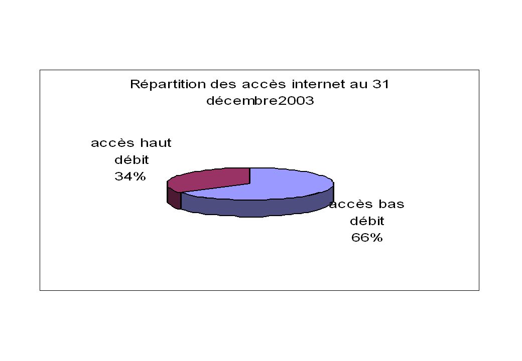
Evolution France VOLUMES Au 31 décembre 2003 Au 31 mars 2004
Au 30 juin Evolution 2T04/1T04 Parc en unités - dont Internet bas débit + 1% - 6,5% - dont Internet haut débit (y compris les abonnés via le câble) + 11,8%
 ,8%")
7
Au 31 décembre 2003 Au 31 mars 2004 Au 30 juin Evolution 2T04/1T04 CHIFFRE d’AFFAIRES (en millions d’€) - dont Internet bas débit 636 225 659 201 + 3,5 % - 11,1 % - dont Internet haut débit (y compris le câble) 411 458 + 11,4 %
 ,4 %")
8
Le nombre d’abonnements haut débit a crû de 12% au 2ème trimestre 2004, pour atteindre les 5 millions, dont par le câble. => On peut estimer que la France compte plus de six millions d’abonnements haut débit à la fin de l’année 2004 (contre 3,6 millions fin 2003)
")
9
Evolution de l’ADSL

10
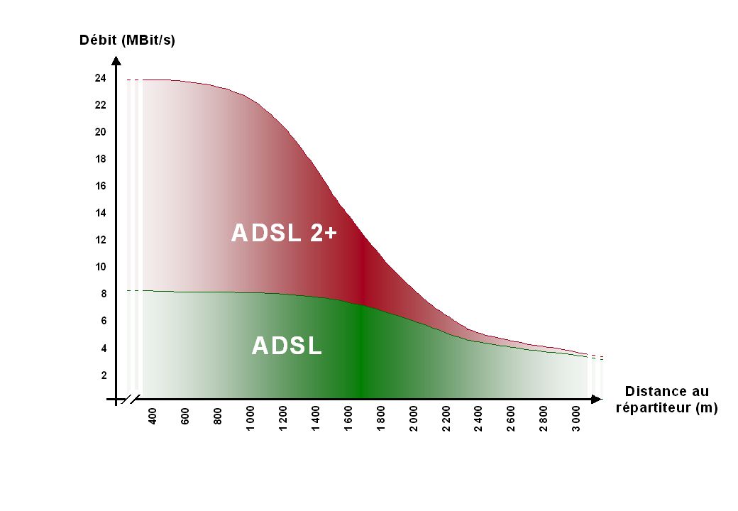
Les prochaines années verront une montée en débit des offres proposées
Source : Comité d’Experts mandaté par l'Autorité L'innovation technologique permet d'envisager d'une part une augmentation des débits offerts (ADSL 2+, VDSL, FTTH) et d'autre part une extension de la couverture à partir des centraux téléphoniques (RE-ADSL)
 et d autre part une extension de la couverture à partir des centraux téléphoniques (RE-ADSL)")
11
Le READSL ou Reach Extended ADSL est une variante de l'ADSL qui utilise les mêmes normes de modulation que son cousin, la DMT, ou Discrete Multi Tone. L'idée du READSL est de "booster" la partie la plus basse du spectre, en envoyant plus d'énergie entre 25 et 200 kHz. Cette technologie doit permettre de prolonger de 10 % la portée des lignes pour des débits de 128 et 512 kbit/s. Les abonnés situés dans une zone ADSL mais se trouvant jusqu'alors trop loin du central ("zones d'ombre") pourront ainsi mieux bénéficier des services offerts. L'homologation de cette norme est en cours de finalisation à l'UIT
 pourront ainsi mieux bénéficier des services offerts. L homologation de cette norme est en cours de finalisation à l UIT.")
12
Basée sur la même technologie (les signaux VDSL sont transportés sur une paire de cuivre, simultanément et sans interférence avec la voix téléphonique), le VDSL (Very high bit rate DSL) permet d'atteindre de très hauts débits : il peut fournir jusqu'à 52 Mbit/s (descendant) et 2 Mbit/s (montant) Le VDSL permet l'accés à des applications requérant une bande passante plus conséquente : la vidéo de haute qualité en premier lieu (HDTV et video à la demande), les services interactifs, ... Inconvénient du dispositif : portée (la distance entre le réseau à haut débit et l'utilisateur) limitée à 300 m. en configuration de flux descendant maximal. Ceci, pour l'instant, restreint considérablement le nombre d'abonnés pouvant être raccordés directement via le réseau de distribution.
, les services interactifs, ... Inconvénient du dispositif : portée (la distance entre le réseau à haut débit et l utilisateur) limitée à 300 m. en configuration de flux descendant maximal. Ceci, pour l instant, restreint considérablement le nombre d abonnés pouvant être raccordés directement via le réseau de distribution.")
13
VDSL – Network architecture
Local exchange VDSL VDSL Street Street Remote Cabinet Cabinet Optical Platform Customers Customers Prolongation vers un bâtiment très proche

14
Dès 2005, l'arrivée de l'ADSL 2+ permettra de franchir les 10 Mbit/s
L'utilisation de l’ADSL 2+ est autorisée dans le réseau de France Télécom depuis le 13 octobre 2004. Cette technologie permet de doubler le débit maximal pour les lignes courtes. Les offres DSL devraient donc continuer à monter en débit 2005. En 2004, l'Autorité a autorisé France Télécom à s'inscrire dans ce mouvement, en rendant des avis favorables aux homologations : - d'IP/ADSL 2 Mbit/s - et d'IP/ADSL Max.

16
ADSL: adapté à la SDSL : interconnexion de LAN distants (pourquoi ?) Pourquoi le SDSL offre-t-il globalement des débits inférieurs ?
 Pourquoi le SDSL offre-t-il globalement des débits inférieurs")
17
Le dégroupage de la boucle locale de cuivre

18
Le dégroupage de la boucle locale de cuivre permet aux opérateurs alternatifs d'accéder à la paire de cuivre téléphonique "nue", et d'y connecter leurs propres équipements actifs (DSLAM, modems) Le dégroupage permet donc aux opérateurs alternatifs de s'affranchir complètement des équipement actifs de France Télécom : - les débits peuvent être différents de ceux de l'opérateur historique ; - les packs "triple play" se développent ; - les tarifs des offres SDSL entreprises baissent rapidement.

19
La technologie ADSL Centre local Répartiteur Filtre Client
Vers le centre de commutation local Modem Filtre DSLAM Client MUX SDH, ATM Autres centres locaux Point de Concentration

20
Une concurrence réglementée
Accès réglementé au réseau existant : La revente ; Le dégroupage de la boucle locale ; USA : 1996 Europe : prévu dès 1998 dans certains pays, pour les autres pays Règlement de la Commission Européenne de décembre 2000 avec mise en œuvre début 2001.

21
Quatre formes de dégroupage
Régulation au niveau national (en France, l’ART) : Dégroupage total : location d’une ligne dans son intégralité Accès partagé : location de la partie haute du spectre pour fournir des services hauts débit uniquement. Accès au débit : « interconnexion » IP/ATM. Revente
 : Dégroupage total : location d’une ligne dans son intégralité. Accès partagé : location de la partie haute du spectre pour fournir des services hauts débit uniquement. Accès au débit : « interconnexion » IP/ATM. Revente.")
22
ADSL = nouveau mode d’accès pour: (particuliers + entreprises) sans QoS Interconnexion de réseaux locaux (entreprises) avec QoS Le réseau d’accès nécessite un réseau de collecte
 sans QoS Interconnexion de réseaux locaux (entreprises) avec QoS Le réseau d’accès nécessite un réseau de collecte")
23
Accès à Internet bas débit
Repose sur le réseau téléphonique commuté (RTC); Appel vers un numéro non géographique (0860…) Internautes : Couverture potentielle : ~100% (la pénétration du téléphone) ; 7,3 M d’abonnés actifs en juin 2003 (mais en décroissance pour la 1ère fois en 2004).
; Appel vers un numéro non géographique (0860…) Internautes : Couverture potentielle : ~100% (la pénétration du téléphone) ; 7,3 M d’abonnés actifs en juin (mais en décroissance pour la 1ère fois en 2004).")
24
Accès à Internet bas débit

25
Le marché des FAI Evolution des offres Offres tout payant (com + accès) Offres accès gratuit (com payantes) Offres forfait limité payant Offres forfait illimité payant. Faillites et fusions. Aujourd’hui, 5 FAI représentent 80% du marché (Wanadoo, Club Internet, Free, Tiscali, AOL). La recherche de la rentabilité.
. La recherche de la rentabilité.")
26
Sources de revenus des FAI
Abonnements Publicité et mise en valeur des données clients Revenus sur les appels téléphoniques (à partager avec les opérateurs téléphoniques).
.")
27
Le marché de la collecte
Acteurs : opérateurs de réseau : France Télécom, Télécom Développement, Ldcom, … Concurrence élevée : Petit nombre d’acheteurs (marché des FAI très concentré) ; « Coût de changement » faibles. Croissance ralentie de la demande avec le développement de l’ADSL.
 ; « Coût de changement » faibles. Croissance ralentie de la demande avec le développement de l’ADSL.")
28
L’Internet Architecture end to end : L’intelligence est dans les extrémités du réseau, pas dans le cœur du réseau. C’est une plateforme neutre : il n’y a pas de discrimination entre les paquets. Par conséquent, le « réseau » ne peut pas favoriser certains paquets au détriment d’autres.

29
La croissance d’Internet
1977: 111 hosts on Internet 1981: 213 hosts 1983: 562 hosts 1984: 1,000 hosts 1986: 5,000 hosts 1987: 10,000 hosts 1989: 100,000 hosts 1992: 1,000,000 hosts 2001: 150 – 175 million hosts 2002: over 200 million hosts

30
La taille de l’Internet (connu) - nombre d’hosts
 - nombre d’hosts")
31
1 050 000 lignes étaient dégroupées au 1er octobre 2004 …
Nombre de lignes dégroupées Le dégroupage représente 20% des lignes DSL en France au 1er octobre 2004 La France est en première place européenne pour le nombre de lignes DSL dégroupées.

32
… et 50 % de la population française avait accès au dégroupage.
Nombre de répartiteurs équipés pour le dégroupage

33
Couverture du dégroupage au 1er octobre 2004
Le dégroupage couvre toutes les grandes villes et une partie des villes de taille intermédiaire. Cependant, 13 départements ne sont pas encore concernés

34
Plusieurs opérateurs proposent désormais des offres fondées sur le dégroupage total.
Elles permettent aux consommateurs qui le souhaitent de n'avoir qu'une seule facture, et un seul opérateur pour la haut débit, la voix, et l'abonnement. Des discussions sont en cours pour permettre l’amélioration du dégroupage total: délais de livraison, portage immédiat du numéro de téléphone, meilleure protection des consommateurs.

35
Nombre de lignes en dégroupage total 51 421

36
La couverture géographique du haut débit
La couverture de la population La couverture des entreprises L’extension géographique de la concurrence Le rôle de l’action publique locale

37
La couverture géographique du haut débit
France Télécom annonce pouvoir couvrir en DSL 96% de la population à fin 2007 Pour assurer la couverture des zones résiduelles, dont le pourcentage exact est aujourd’hui difficile à estimer (car les technologies DSL s’améliorent de jour en jour), il existe plusieurs possibilités : - les évolutions de la technologie DSL (Re-ADSL) - les expérimentations du dégroupage au sous-répartiteur - les autres technologies, comme la BLR … (?)
, il existe plusieurs possibilités : - les évolutions de la technologie DSL (Re-ADSL) - les expérimentations du dégroupage au sous-répartiteur. - les autres technologies, comme la BLR … ( )")
38
L’extension géographique de la concurrence
Des expérimentations de dégroupage au sous-répartiteur sont lancées, ce qui permettra d’étendre la couverture géographique, et de toucher une population encore plus nombreuse, en particulier les entreprises situées dans des zones d’activités isolées

39
FTTB: Fiber To The Building FTTC: Fiber To The Curb [Fibre jusqu'au trottoir]
Technologie qui amène le réseau en fibre optique jusqu'au voisinage de l'abonné. FTTH: Fiber To The Home [Fibre jusqu'au domicile] Technologie qui amène le réseau en fibre optique jusque chez l'abonné.
![FTTB: Fiber To The Building FTTC: Fiber To The Curb [Fibre jusqu au trottoir]](http://slideplayer.fr/slide/3104813/11/images/39/FTTB%3A+Fiber+To+The+Building+FTTC%3A+Fiber+To+The+Curb+%5BFibre+jusqu+au+trottoir%5D.jpg "Technologie qui amène le réseau en fibre optique jusqu au voisinage de l abonné. FTTH: Fiber To The Home [Fibre jusqu au domicile] Technologie qui amène le réseau en fibre optique jusque chez l abonné.")
40
technologie ADSL

41
ADSL Asymmetric Digital Subscriber Lines (ADSL) are used to deliver high-rate digital data over existing ordinary phone-lines (POTS: plain old telephone service). A new modulation technology called Discrete Multitone (DMT) allows the transmission of high speed data. ADSL facilitates the simultaneous use of normal telephone services and high speed data transmission, eg., video.
 are used to deliver high-rate digital data over existing ordinary phone-lines (POTS: plain old telephone service). A new modulation technology called Discrete Multitone (DMT) allows the transmission of high speed data. ADSL facilitates the simultaneous use of normal telephone services and high speed data transmission, eg., video.")
42
Discrete Multitone (DMT)
The basic idea of DMT is to split the available bandwidth into a large number of subchannels. DMT is able to allocate data so that the throughput of every single subchannel is maximized. If some subchannel can not carry any data, it can be turned off and the use of available bandwidth is optimized.

43
ADSL (ITU G.992.1) ADSL repartition spectrale
Power POTS POTS POTS DATA DATA DATA Upstream Upstream Upstream Downstream Downstream Downstream 300 Hz 300 Hz 300 Hz 3,4 kHz 3,4 kHz 3,4 kHz 22 kHz 22 kHz 22 kHz 133kHz 133kHz 133kHz 203 kHz 203 kHz 203 kHz 1.1 MHz 1.1 MHz 1.1 MHz Frequency FDD: Frequency Division Duplexing =>no interferences between Up and Down 2 ADSL existent en fait: ADSL G (G.lite) and G (G.full) !!
 and G (G.full) !!")
44
ADSL utilise le Discrete Multi Tone Line Code (DMT)
ADSL utilise jusqu’à 255 fréquences (bins) kHz entre chaque fréquence (tone) Each tone is encoded with up to 15 bits The lower tones (blue) are used for upstream signal, the higher tones (red) are used for downstream signal ADSL bins Frequency Interleaving : entrelacement – De-Interleaving !!
 kHz entre chaque fréquence (tone) Each tone is encoded with up to 15 bits. The lower tones (blue) are used for upstream signal, the higher tones (red) are used for downstream signal. ADSL bins. Frequency. Interleaving : entrelacement – De-Interleaving !!")
45
G.Lite Up to 1.536 Mbps Down, 512 kbps Up
Débit inférieur sur de plus longues distances Complementaire à l’ADSL “internal” G.Lite PC comes with built-in G.Lite modem Together with analog (V.90)
")
46
DSL Frequency Spectrum
ADSL POTS Downstream Upstream 1.5Mbps 8 Mbps 0.3 3.5 20 140 552 1104 Frequency (kHz) G.Lite
 G.Lite.")
47
Architecture INTERNET
Backbone A Backbone B peering ISP 1 ISP n1 ISP N ISP n2 Réseaux de collecte (opérateurs) transit Réseaux d’accès (vers les clients)
 transit. Réseaux d’accès (vers les clients)")
48
Residential Broadband Service Model
Providers Network Access Provider Customer premise Content Providers Regional Broadband Network Access network ISP (POP) Telco CO/Cable Hub Internet Regional Operation Center Corporate networks
 Telco CO/Cable Hub. Internet. Regional. Operation. Center. Corporate. networks.")
49
Employer’s Corporate Network
ADSL ATM Network ISP Internet Content Provider Local “Native ATM” Service Employer’s Corporate Network Tunnel RAS

50
Le réseau d’accès ou boucle locale
Définition : « the last mile », la partie d’un réseau qui relie l’abonné au « réseau général », c’est-à-dire la partie du réseau comprise entre la prise (de téléphone) et le premier équipement actif du réseau (répartiteur du commutateur de rattachement). abonné commutateur ou multiplexeur Réseau Transport Boucle locale (filaire, radio, etc.)
 et le premier équipement actif du réseau (répartiteur du commutateur de rattachement). abonné. commutateur. ou multiplexeur. Réseau Transport. Boucle locale (filaire, radio, etc.)")
51
Schéma fonctionnel d’un DSLAM
DSLAM: Digital Subscriber Line Access Multiplexer POTS/ISDN port POTS ISDN Split. N Splitter ADSL modem Copper access line ADSL + POTS/ISDN ATM network STM-1 ATM cells DSLAM

52
1 alternative à cette architecture: IP ADSL avec IP DSLAM !
ADSL ATM XDSL IAD ATM IP Commercial Residential ISP1 ISP2 DSLAM Switch 1 alternative à cette architecture: IP ADSL avec IP DSLAM !

54
Data Rate Wire Gauge Distance Wire Size Distance 1.5 or 2 Mbps 24 AWG 18,000 ft 0.5 mm 5.5 km 26 AWG 15,000 ft 0.4 mm 4.6 km 6.1 Mbps 12,000 ft 3.7 km 9,000 ft 2.7 km

55
The standard (ANSI) ADSL system uses 256 frequency channels for the downstream data and 32 channels for the upstream. Interleaving and De-Interleaving Performance (comparison with Leased Line) Bridge taps
 Bridge taps.")
56
xDSL vs LL: quality contest
ADSL/SDSL Processing Delay (due to Packet Switching technology) Jitter (idem) No xDSL protection in the access network xDSL reach limited to few Km No bandwidth guarantee (ADSL) Availability Leased Lines Minimum delay (TDM) Minimum jitter Protection always possible No risk of cell loss Bandwidth is guaranteed
 Jitter (idem) No xDSL protection in the access network. xDSL reach limited to few Km. No bandwidth guarantee (ADSL) Availability. Leased Lines. Minimum delay (TDM) Minimum jitter. Protection always possible. No risk of cell loss. Bandwidth is guaranteed.")
57
Leased Lines versus xDSL
xDSL has some limitations in terms of… Bandwidth Loop length SLA’s Overbooking always takes place Leased Lines have arguments… Any bandwidth available No length limitations High SLA’s Proven techology for mission critical applications (no overbooking)
")
58
Description de la chaîne de liaison
vue de l’internaute Dégroupage (option 1) ADSL Connect ATM (option 3) France Télécom Opérateur tiers FAI Internaute Offre concurrente d’IP/ADSL Le client achète au FAI l’ensemble accès ADSL + abonnement ADSL IP/ADSL : accès + collecte (option 5)
 ADSL Connect ATM (option 3) France Télécom. Opérateur. tiers. FAI. Internaute. Offre concurrente d’IP/ADSL. Le client achète au FAI l’ensemble accès ADSL + abonnement ADSL. IP/ADSL : accès + collecte (option 5)")
59
À destination des opérateurs :
L’option 1 : offre d ’accès à la paire de cuivre, sous deux formes (dégroupage total, accès partagé) ; permet à l’opérateur la maîtrise complète des offres fournies au client final ; statut réglementaire : une offre de référence de France Télécom, sur laquelle l ’ART peut imposer des modifications
 ; permet à l’opérateur la maîtrise complète des offres fournies au client final ; statut réglementaire : une offre de référence de France Télécom, sur laquelle l ’ART peut imposer des modifications.")
60
À destination des opérateurs :
L’option 3 : offre de revente de la ligne ADSL de France Télécom et collecte de trafic à des niveaux intermédiaires du réseau de France Télécom à destination des opérateurs, complémentaire du dégroupage ; permet une concurrence sur les offres IP/ADSL à destination des FAI statut réglementaire : offre d’accès spécial ; l’ART peut en particulier régler les différends entre opérateurs sur ses conditions techniques et tarifaires.

61
Option 3 FT: TURBO DSL - environ 41 plaques sur le territoire (10 IDF dont 3 pour Paris) - l’opérateur client choisit des portes à un débit donné (multiple de 30 Mb/s) pour une ou plusieurs plaques - FT amène son lien (STM-1 par exemple) jusqu’au local de l’opérateur (boitier RAD d’extrémité) - l’opérateur propose à ces clients différents débits ADSL 0,5 C (0,6 Mb/s sens montant, C= Crête, VBR3), ADSL 2G (émulation de LS), SDSL 1C, … · exemple: offre FT 1C (1,2M/320K), sens descendant : PCR= 2867 cells/s (1216K), SCR=604 cellules/s (256K), MBS=1300 cellules (62koctets entête IP compris) sens montant : PCR= 754 cells/s (320K), SCR=604 cellules/s (256K), MBS=1300 cellules (62koctets entête IP compris) - FT (police) vs l’opérateur (TS dans le sens descendant): boitier RAD face à face
 - l’opérateur client choisit des portes à un débit donné (multiple de 30 Mb/s) pour une ou plusieurs plaques - FT amène son lien (STM-1 par exemple) jusqu’au local de l’opérateur (boitier RAD d’extrémité) - l’opérateur propose à ces clients différents débits ADSL 0,5 C (0,6 Mb/s sens montant, C= Crête, VBR3), ADSL 2G (émulation de LS), SDSL 1C, … · exemple: offre FT 1C (1,2M/320K), sens descendant : PCR= 2867 cells/s (1216K), SCR=604 cellules/s (256K), MBS=1300 cellules (62koctets entête IP compris) sens montant : PCR= 754 cells/s (320K), SCR=604 cellules/s (256K), MBS=1300 cellules (62koctets entête IP compris) - FT (police) vs l’opérateur (TS dans le sens descendant): boitier RAD face à face")
62
À destination des fournisseurs d ’accès Internet :
L’option 5 : deux composantes : l ’accès IP/ADSL (offre de revente de la Ligne ADSL de France Télécom) et la collecte IP/ADSL (les flux de trafic) offre soumise à homologation.
 et la collecte IP/ADSL (les flux de trafic) offre soumise à homologation.")
63
En vert: limite de responsabilité de FT
Paire de cuivre DSLAM BAS Réseau transport IP ATM Fitre Abonné FAI I N T E R IP/ADSL + Collecte IP/ADSL régionale, 17 régions (option 5) (offre de revente - marché résidentiel et SoHo) IP/ADSL + Collecte IP/ADSL nationale (option 5) Accès ADSL Transport ATM puis IP Abonnés
 (offre de revente - marché résidentiel et SoHo) IP/ADSL + Collecte IP/ADSL nationale (option 5) Accès ADSL. Transport ATM puis IP. Abonnés.")
64
Paire de cuivre DSLAM BAS Réseau transport IP Dorsal ATM Filtre Modem ADSL Abonné FAI @ Dégroupage (option 1) ADSL Connect ATM régionale, 41 plaques (option 3) (offre opérateurs - marché résidentiel et entreprises) Accès ADSL Transport ATM puis IP Abonnés
 ADSL Connect ATM régionale, 41 plaques (option 3) (offre opérateurs - marché résidentiel et entreprises) Accès ADSL. Transport ATM puis IP. Abonnés.")
65
Les objectifs de l’Autorité en faveur du développement de l’ADSL résidentiel
Une concurrence effective sur l’ensemble des segments de la chaîne de valeur L’accès : la décision du 16 avril 2002 sur les conditions tarifaires et opérationnelles du dégroupage (accès totalement dégroupé et accès partagé) La collecte et le transport : la nécessité d’une offre option 3, permettant aux opérateurs de compléter leur déploiement au titre du dégroupage et de concurrencer les offres option 5 de France Télécom (IP/ADSL) Le service Internet : permettre une viabilité des offres ADSL des FAI, tout en assurant aux opérateurs des conditions d’entrée viables sur le marché, au travers du dégroupage et de l’option 3
 La collecte et le transport : la nécessité d’une offre option 3, permettant aux opérateurs de compléter leur déploiement au titre du dégroupage et de concurrencer les offres option 5 de France Télécom (IP/ADSL) Le service Internet : permettre une viabilité des offres ADSL des FAI, tout en assurant aux opérateurs des conditions d’entrée viables sur le marché, au travers du dégroupage et de l’option 3.")
66
Evolution (chez l’utilisateur)
Coax/Composites MPEG/IP Over 100BaseT TCP/IP Over 10/100BaseT ADSL2+ IAD Traditional POTS

67
Après le niveau physique (trivial) ….
…. Les protocoles réseau (moins trivial…): PPP point to point protocol : un protocole pour gérer les accès distants et la transition entre: . les LAN aux extrémités et . les réseaux d’accès et de transport au centre
: PPP point to point protocol : un protocole pour gérer les accès distants. et la transition entre: . les LAN aux extrémités et. . les réseaux d’accès et de transport au centre.")
68
Remote Node PPP

69
Point-to-Point Connections with PPP
When you create a dialup connection to RAS, you must use a protocol to communicate. The protocol most often used to create the point-to-point connection is Point-to-Point Protocol (PPP). It is based on an older protocol know as the Serial Line Internet Protocol (SLIP).
. It is based on an older protocol know as the Serial Line Internet Protocol (SLIP).")
70
Point-to-Point Connections with PPP
PPP offers several advanced capabilities. When it is used to connect with a remote network, it encapsulates the upper-layer protocols. PPP supports both Password Authentication Protocol (PAP) and Challenge Handshake Authentication Protocol (CHAP), which both prompt users to log on to establish a connection using encryption or clear text passwords.
 and Challenge Handshake Authentication Protocol (CHAP), which both prompt users to log on to establish a connection using encryption or clear text passwords.")
71
Phase 1: Link Control Protocol (LCP) Set up and release connections
PPP – Two phase control Phase 1: Link Control Protocol (LCP) Set up and release connections Status monitoring and testing of the link Negotiate QOS Authentication of peers Phase 2: Network Control Protocol (NCP) Adaptation to the Network Protocol (IP e.g.) Dial back is handled at LCP layer
 Set up and release connections. Status monitoring and testing of the link. Negotiate QOS. Authentication of peers. Phase 2: Network Control Protocol (NCP) Adaptation to the Network Protocol (IP e.g.) Dial back is handled at LCP layer.")
72
LCP State Machine

73
PPP Example Authenticating Network Layer Establishment
LCP [Configure-Request (CO’s)] LCP [Configure-ACK] CHAP Challenge [M] IPCP [Configure-Request (X,Y)] IPCP [Configure-ACK] PPP [Protocol=x’0021 (IP Packet)] LCP [Terminate-Request] LCP [Terminate-ACK] Link Establishing Authenticating Exchanging Data at Network Layer Link Termination Network Layer Establishment Network Layer Termination CHAP Response [HASH (M||Secret)]
] LCP [Configure-ACK] CHAP Challenge [M] IPCP [Configure-Request (X,Y)] IPCP [Configure-ACK] PPP [Protocol=x’0021 (IP Packet)] LCP [Terminate-Request] LCP [Terminate-ACK] Link Establishing. Authenticating. Exchanging Data at Network Layer. Link Termination. Network Layer Establishment. Network Layer Termination. CHAP Response [HASH (M||Secret)]")
74
PPP in real life :53:45:4e:44:17 -> 20:53:45:4e:44:17 PPP LCP PPP LCP Configuration Request :52:45:43:56:17 -> 20:52:45:43:56:17 PPP LCP PPP LCP Configuration Request :53:45:4e:44:17 -> 20:53:45:4e:44:17 PPP LCP PPP LCP Configuration ACK :52:45:43:56:17 -> 20:52:45:43:56:17 PPP LCP PPP LCP Configuration Reject :53:45:4e:44:17 -> 20:53:45:4e:44:17 PPP LCP PPP LCP Configuration Request :52:45:43:56:17 -> 20:52:45:43:56:17 PPP LCP PPP LCP Configuration ACK :53:45:4e:44:17 -> 20:53:45:4e:44:17 PPP LCP PPP LCP Identification :52:45:43:56:17 -> 20:52:45:43:56:17 PPP CHAP PPP CHAP Challenge :53:45:4e:44:17 -> 20:53:45:4e:44:17 PPP CHAP PPP CHAP Response :52:45:43:56:17 -> 20:52:45:43:56:17 PPP CHAP PPP CHAP Success :53:45:4e:44:17 -> 20:53:45:4e:44:17 PPP CCP PPP CCP Configuration Request :53:45:4e:44:17 -> 20:53:45:4e:44:17 PPP IPCP PPP IPCP Configuration Request :52:45:43:56:17 -> 20:52:45:43:56:17 PPP IPCP PPP IPCP Configuration Request :53:45:4e:44:17 -> 20:53:45:4e:44:17 PPP IPCP PPP IPCP Configuration ACK :53:45:4e:44:17 -> 20:53:45:4e:44:17 PPP IPCP PPP IPCP Configuration Request :52:45:43:56:17 -> 20:52:45:43:56:17 PPP IPCP PPP IPCP Configuration NACK :53:45:4e:44:17 -> 20:53:45:4e:44:17 PPP IPCP PPP IPCP Configuration Request :52:45:43:56:17 -> 20:52:45:43:56:17 PPP IPCP PPP IPCP Configuration ACK :52:45:43:56:17 -> 20:52:45:43:56:17 PPP LCP PPP LCP Echo Request :53:45:4e:44:17 -> 20:53:45:4e:44:17 PPP LCP PPP LCP Echo Reply :53:45:4e:44:17 -> 20:53:45:4e:44:17 PPP LCP PPP LCP Termination Request :52:45:43:56:17 -> 20:52:45:43:56:17 PPP LCP PPP LCP Termination ACK

75
Authentication – PAP and CHAP
PAP Authentication (RFC 1334) Authentication-Request Messages (Use name, password) Authentication-Response Message (Accept or Reject) Server Client CHAP Authentication (RFC 1994) Challenge Message Response Message: Hash (Challenge Message + Secret) Authentication-Response Message (Accept or Reject) Server Client
 Authentication-Request Messages (Use name, password) Authentication-Response Message (Accept or Reject) Server. Client. CHAP Authentication (RFC 1994) Challenge Message. Response Message: Hash (Challenge Message + Secret) Authentication-Response Message (Accept or Reject) Server. Client.")
76
Accès distant – 2 modes principaux:. permanent (LS, XDSL, …)
Accès distant – 2 modes principaux: . permanent (LS, XDSL, …) . dial up (RAS, NAS, par RTC, RNIS)
 . dial up (RAS, NAS, par RTC, RNIS)")
77
Dial-UP: Traditional Remote Access
Problèmes et limites: Dimensionnement de l’infrastructure du siège Appels Long-distance requis PPP PPP header IP original IP header IP payload IP payload payload message payload PC NAS Telephone Network Increased call capacity affects corporate infrastructure Additional incoming lines are required when increasing call capacity. This affects the infrastructure, and also the NAS. Evolving broadband technologies require NAS update New broadband connection techniques require an update or replacement of the NAS. Long-distance calls required Long-distance calls are required on the legacy phone network. Network Access Server Corporate LAN

78
L2TP – Layer 2 Tunneling Protocol
Fusion de Cisco L2F et Microsoft PPTP Standard - RFC 2661 Remote dialup VPN access Tunnels PPP sur UDP/IP Enables local distance dial access No extra software sur le client distant PPP interface L2TP UDP/IP stack Merge of Cisco L2F and Microsoft PPTP The L2TP protocol as specified in RFC 2661 is a merger of the Cisco L2F and the Microsoft PPTP protocol. The ”Compulsory Tunneling” mode of L2TP resembles L2F while the ”Voluntary Tunneling” mode has borrowed a lot from PPTP. Industry standard - RFC 2661 The RFC dates from mid-1999, and a number of interoperability tests have been performed. Remote dialup VPN access L2TP creates a Virtual Private Network by accessing a corporate LAN through a dial-up connection. Tunnels PPP frames over UDP/IP L2TP operates on PPP frames, which are tunneled over UDP/IP. Enables local distance dial access Since L2TP uses the public Internet, local distance dial-up connections to an ISP can be used. No extra software on remote client The remote client is communicating by means of the PPP protocol. This is exactly the same setup as when connecting to a normal ISP. Configuration Exemple

79
Tunneling Establishment
Voluntary tunneling: Tunnel is created by the client (user) User sends packets encapsulated in the tunneling protocol (L2TP, PPTP) Compulsory tunneling: Tunnel is created without any action from the client Client sends PPP packets to LAC (e.g., ISP), which encapsulates them in the tunneling protocol (L2TP, PPTP)
 User sends packets encapsulated in the tunneling protocol (L2TP, PPTP) Compulsory tunneling: Tunnel is created without any action from the client. Client sends PPP packets to LAC (e.g., ISP), which encapsulates them in the tunneling protocol (L2TP, PPTP)")
80
L2TP Compulsory Tunneling
Traditional NAS work is split between LAC and LNS Remote computer does not control the tunnel IP new IP header L2TP L2TP message header PPP PPP header PPP IP payload IP original IP header IP payload message payload payload PC Internet ou Telco LAC LNS Telephone Network Traditional NAS work is split between LAC and LNS This enables the use of local distance dial-in connections to the LAC. It also means that the corporate infrastructure (i.e. number and characteristics of incoming lines) remains unmodified if call capacity has to be increased. Remote computer does not control the tunnel The remote client operates as with a normal PPP connection to an ISP, and is not aware of the tunnel. L2TP Tunnel IP payload L2TP Access Concentrator L2TP Network Server Corporate LAN
 remains unmodified if call capacity has to be increased. Remote computer does not control the tunnel. The remote client operates as with a normal PPP connection to an ISP, and is not aware of the tunnel. L2TP Tunnel. IP. payload. L2TP. Access. Concentrator. L2TP. Network. Server. Corporate. LAN.")
81
L2TP Voluntary Tunneling
Virtual dial-up connection Remote computer controls the tunnel IP new IP header L2TP L2TP message header PPP PPP header IP original IP header IP payload message payload payload Internet PC + LAC LNS Virtual dial-up connection The L2TP connection is established directly from the client to the LNS. The client connects to the LNS in the same way as when dialing into an ISP with a modem. Remote computer controls the tunnel The remote client is aware of the connection made to the LNS through the action of having initiated a virtual dial-up connection. The client can decide which traffic will be sent into the tunnel, i.e. based on routing information. L2TP Tunnel PC with L2TP Client L2TP Network Server Corporate LAN

82
Tunneling to a Virtual Private Network (VPN)
VPN describes remote nodes that access a network via the Internet (or a Telco operator) in a secure fashion. 2 VPN types: VPN-IP and security is provided by tunneling protocols with encryption (IPSEC e.g.)
 in a secure fashion. 2 VPN types: VPN-IP and security is provided by tunneling protocols with encryption (IPSEC e.g.)")
83
Tunneling to a Virtual Private Network (VPN)
VPN is available to clients who connect to the Internet through nearly any type of link. Whether the client connects via ISDN, DSL, cable modem, or dialup line, a VPN session can usually be created. VPN creates a virtual point-to-point connection to the RAS. Tunneling works by encapsulating data within IP packets in an encrypted format.

84
Tunneling to a Virtual Private Network (VPN)
")
85
Layer 2 Tunneling Protocol
L2TP is an extension of PPP that supports multiple protocols. Two servers provide an L2TP tunnel: the first is an L2TP access concentrator (LAC), which is simply a NAS. The second is an L2TP network server (LNS), which provides the L2TP service.
, which is simply a NAS. The second is an L2TP network server (LNS), which provides the L2TP service.")
86
Tunneling – L2TP Corporate Site A ISP or Telco L2TP Tunnel Local
ISP Access (Leased/Dialup) ISP or Telco LNS (F/R, ATM) Remote Corporate PC LAC L2TP access concentrator (LAC)—An L2TP device that the client directly connects to and whereby PPP frames are tunneled to the L2TP network server (LNS). The LAC needs only implement the media over which L2TP is to operate to pass traffic to one or more LNSs. It may tunnel any protocol carried within PPP. The LAC is the initiator of incoming calls and the receiver of outgoing calls. Analogous to the Layer 2 Forwarding (L2F) network access server (NAS). LAC need only implement the media over which L2TP is to operate to pass traffic to one or more LNS's L2TP network server (LNS)—Termination point for L2TP tunnel and access point where PPP frames are processed and passed to higher layer protocols. An LNS operates on any platform capable of PPP termination. The LNS handles the server side of the L2TP protocol. L2TP relies only on the single media over which L2TP tunnels arrive. The LNS may have a single LAN or WAN interface, yet still be able to terminate calls arriving at any of the LACs full range of PPP interfaces (asynchronous, synchronous, ISDN, V.120, etc.). The LNS is the initiator of outgoing calls and the receiver of incoming calls. Analogous to the Layer 2 Forwarding (L2F) home gateway (HGW). LNS operates on any platform capable of PPP termination. L2TP is connection oriented. RFC 2661 IP RADIUS Server PPP L2TP L2TP is implemented only by LNS and LAC, completely transparent to the clients Different endpoints for L2 and PPP
 ISP or Telco. LNS. (F/R, ATM) Remote. Corporate. PC. LAC. L2TP access concentrator (LAC)—An L2TP device that the client directly connects to and whereby PPP frames are tunneled to the L2TP network server (LNS). The LAC needs only implement the media over which L2TP is to operate to pass traffic to one or more LNSs. It may tunnel any protocol carried within PPP. The LAC is the initiator of incoming calls and the receiver of outgoing calls. Analogous to the Layer 2 Forwarding (L2F) network access server (NAS). LAC need only implement the media over which L2TP is to operate to pass traffic to one or more LNS s. L2TP network server (LNS)—Termination point for L2TP tunnel and access point where PPP frames are processed and passed to higher layer protocols. An LNS operates on any platform capable of PPP termination. The LNS handles the server side of the L2TP protocol. L2TP relies only on the single media over which L2TP tunnels arrive. The LNS may have a single LAN or WAN interface, yet still be able to terminate calls arriving at any of the LACs full range of PPP interfaces (asynchronous, synchronous, ISDN, V.120, etc.). The LNS is the initiator of outgoing calls and the receiver of incoming calls. Analogous to the Layer 2 Forwarding (L2F) home gateway (HGW). LNS operates on any platform capable of PPP termination. L2TP is connection oriented. RFC IP. RADIUS. Server. PPP. L2TP. L2TP is implemented only by LNS and LAC, completely transparent to the clients. Different endpoints for L2 and PPP.")
87
L2TP + IPSec Example L2TP L2TP + IPSec PPP IP TCP Data IP UDP L2TP PPP
ESP UDP L2TP PPP IP TCP Data ESP

88
Layer 2 Tunneling Modes Compulsory L2 Tunnelling
Voluntary L2 Tunnelling

89
Protocol Stack PPP Negotiation and Tunnel Establishment
LAC LNS

90
Layer 2 Tunneling Protocol (L2TP)
Goal: Tunnel PPP frames between remote system (LAC client) and LNS located at LAN. Encapsulate a given network layer protocol (e.g., IP, IPX) inside PPP to cryptographically protect the PPP frames (L2TP) and to encapsulate the data inside a tunneling protocol (e.g., IP) Most popular Applicable over the internet IP PPP L2TP
 and LNS located at LAN. Encapsulate a given network layer protocol (e.g., IP, IPX) inside PPP to cryptographically protect the PPP frames (L2TP) and to encapsulate the data inside a tunneling protocol (e.g., IP) Most popular. Applicable over the internet. IP. PPP. L2TP.")
91
Control channel (reliable): control sessions and tunnel
L2TP Protocol LAC LNS Control Session 1 (Call ID 1) Session 2 (Call ID 2) Tunnel components Control channel (reliable): control sessions and tunnel Data channel (unreliable): created for each call Multiple tunnels may exist between LAC-LNS pair to support different QoS needs
 Session 2 (Call ID 2) Tunnel components. Control channel (reliable): control sessions and tunnel. Data channel (unreliable): created for each call. Multiple tunnels may exist between LAC-LNS pair to support different QoS needs.")
92
Control Messages Establishment, maintenance and clearing of tunnels and calls Utilize a reliable Control Channel within L2TP to guarantee delivery Control message types: Control Connection Management Error Reporting PPP Session Control Sequence numbers (optional): Optional data message sequencing May be used to detect lost packets Data Messages
: Optional data message sequencing. May be used to detect lost packets. Data Messages.")
93
Security Issues Authentication Message Integrity Confidentiality Authorization and audit

94
Security Considerations
Tunnel Endpoint Security Reasonable protection against attacks Designed to provide authentication for tunnel establishment only LAC and LNS MUST share a single secret key Each side uses this same secret when acting as authenticated as well as authenticator Endpoints may optionally perform an authentication procedure of one another during tunnel establishment (CHAP)
")
95
Security Considerations
End to End Security Secure transport in tunnel protects the data within the tunneled PPP packets while transported from the LAC to the LNS Need: security between communicating hosts or applications (IPSec)
")
96
Accès permanents avec l’exemple de l’ADSL

97
Access Protocols PPP Access Non-PPP Access PPPoA: PPP over ATM
PPPoE: PPP over Ethernet Agrégation: L2TP DSL RFC1483 RFC 1483: “Ethernet over ATM” Cisco: aal5snap encapsulation

98
Layer 1 connection = ADSL entre le DSLAM et le modem client
Internet IP Access ATM Network DSLAM PC Mux ATU-R DHCP PPP DNS 10BaseT ADSL (T1.413) Optical SONET (SDH) 100BaseT 100Base X Ou autre
 Optical SONET (SDH) 100BaseT. 100Base X. Ou autre.")
99
Layer 2 connection pour le lien ADSL = ATM circuit (VP/VC) between the customer modem and terminating ATM switch (BAS). Le circuit ATM est défini par un Port physique, VPI, VCI pour chaque segment réseau. Dans la plupart des cas, pour le segment ADSL, la valeur VPI/VCI est standardisé Internet BAS IP Access ATM Network DSLAM PC Mux ATU-R DHCP PPP DNS Ethernet ATM (AAL5) ATM (AAL5) Ethernet Ethernet 10BaseT ADSL (T1.413) Optical SONET 100BaseT 100BaseT
 ATM (AAL5) Ethernet. Ethernet. 10BaseT. ADSL (T1.413) Optical SONET. 100BaseT. 100BaseT.")
100
PPPOE PPPoE and PPPoA are the most common standards.
Authentication is often used as a means to provide username/password security for DSL services. PPPoE and PPPoA are the most common standards. Authentication occurs between the customer PC and the ISP radius (PPP) server. Internet IP Access ATM Network DSLAM PC Mux ATU-R DHCP PPP DNS PPPoE PPPoE Ethernet ATM (AAL5) ATM (AAL5) Ethernet Ethernet 10BaseT ADSL (T1.413) Optical SONET 100BaseT 100BaseT
 server. Internet. IP. Access. ATM. Network. DSLAM. PC. Mux. ATU-R. DHCP. PPP. DNS. PPPoE. PPPoE. Ethernet. ATM (AAL5) ATM (AAL5) Ethernet. Ethernet. 10BaseT. ADSL (T1.413) Optical SONET. 100BaseT. 100BaseT.")
101
If dynamic, the address is assigned by a DHCP server.
The Layer 3 connection for DSL uses IP packets. Each IP packet includes a source address, destination address, and payload. The IP Address is either assigned dynamically, using a protocol such as DHCP, or manually (static). The address resides on the customer’s PC. If dynamic, the address is assigned by a DHCP server. Internet IP Access ADSL (T1.413) 10BaseT 100BaseT Optical SONET ATM Network DSLAM PC Mux ATU-R DHCP PPP DNS IP PPPoE Ethernet ATM (AAL5)
. The address resides on the customer’s PC. If dynamic, the address is assigned by a DHCP server. Internet. IP. Access. ADSL (T1.413) 10BaseT. 100BaseT. Optical SONET. ATM. Network. DSLAM. PC. Mux. ATU-R. DHCP. PPP. DNS. IP. PPPoE. Ethernet. ATM (AAL5)")
102
For DSL, common “applications” are Internet access and email.
Layers 4-7 are commonly grouped together to manage the connection for an actual application. For DSL, common “applications” are Internet access and . High-speed Internet access uses HTTP over TCP. The URL and IP addresses are linked via the DNS server. IP Access ATM Network Internet DHCP PPP DNS Mux DSLAM ATU-R PC PPPoE ADSL (T1.413) 10BaseT 100BaseT Optical SONET Ethernet ATM (AAL5) TCP HTTP
 10BaseT. 100BaseT. Optical SONET. Ethernet. ATM (AAL5) TCP. HTTP.")
103
Alternative intéressante: client PPPoE dans le modem !!
Session PPPoE Home Central Office BAS Broadband Modem PC Client PPPoE Serveur PPPoE RADIUS AAA Server Alternative intéressante: client PPPoE dans le modem !!

104
PPPoA: PPP Over ATM PPPoA fonctionne au-dessus d’un VC ATM
Pas d’autre protocole partageant la même connexion ATM Protocole géré par un routeur (pas d’impact sur les postes clients) Standardisé par ADSL Forum et l’IETF ADSL Forum TR-012 RFC 2364
 Standardisé par ADSL Forum et l’IETF. ADSL Forum TR-012. RFC")
105
End-To-End Protocol Architecture
ICP ISP or corporate network Telco: CO and Core network Client (CPE) IP IP PPPoA PPPoA ATM ADSL
 IP. IP. PPPoA. PPPoA. ATM. ADSL.")
106
PPP Client Authentication
Internet Backbone ISP POP Call setup ATM Network ADSL ISP Data Center Content Provider

107
PPP Client Authentication
Internet Backbone ISP POP PPP CHAP RADIUS authentication ATM Network ADSL ISP Data Center Content Provider

108
PPP Client Authentication
Internet Backbone ISP POP Connection to Internet services ATM Network ADSL ISP Data Center Content Provider

109
PPP Over ATM To Corporate Network, Internet And Local Content Provider
Windows 2000 Corporate Server (RAS) network Home Kid's PC Regional Broadband Network Internet DSL DSLAM modem Gateway PC router Dad's PC Local content
 network. Home. Kid s PC. Regional Broadband. Network. Internet. DSL. DSLAM. modem. Gateway. PC. router. Dad s PC. Local content.")
110
Protocol Stack Layered End-to-End Connectivity
MPLS Core PPP start LAC ISP LNS PE CE PPPox PPP L2TP tunnel ATM PVC ATM PVC Customer-to-ISP IP Connectivity FE Eth Customer PPP end

111
Architecture RFC 1483 (NON PPP)
Cisco BAS Custo- ADSL ATM 6400 CE DSLAM mer PC Modem Switch PE MPLS Core (e.g.) 10BaseT ADSL Copper PE RFC1483 Loop Bridging 1 PVC/ customer ISP CE Si RFC 1483 routing, le CE est un routeur client !! (cas le plus fréquent) @
 10BaseT. ADSL. Copper. PE. RFC1483. Loop. Bridging. 1 PVC/ customer. ISP CE. Si RFC 1483 routing, le CE est un routeur client !! (cas le plus")
112
Problème: isolation des défauts dans une chaîne de liaison complexe
ISP Faults – 22% DSLAM/ATM Faults– 11% Internet IP Access CPE Faults – 40% ATM Network DSLAM PC Mux ATU-R Metallic Faults – 8% DHCP PPP DNS Other – 19% basé sur un échantillon incluant 250,000 tickets.

Présentations similaires


>")

>")


